 Fraunhofer Institute for Reliability and Microintegration IZM
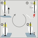
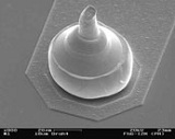
A schematic of the ball bonding procedure is shown in figure 1. This technique is a mechanical single point bumping technology that derives from the conventional ball-wedge bumping process using a wire bonder with modified bond control software. First, the wire is passed through a capillary tube and subjected to an electrical discharge to form a ball (figure 1, step 1; 2: US bonding step), this procedure is the same as for the wire bonding, but the following is different, instead of loop-forming and contacting a 2nd bond the wire clamp is closed after placement of the ball bond and the wire is torn apart (figure 1, step 4). The rupture occurs within the heat affected zone, where the grain structure of the wire is coarser compared to the non-effected state. Figure 2 shows an SEM image of a mechanically applied gold stud bump.
Gold stud bumps can be applied to two interconnection methods, the thermocompression (TC) and the adhesive bonding.